Once again, the internet was my friend and I did a lot of research on how to manage the X Axis on such a small lathe. Some have even put the screw outside the cross slide, but I did not like the idea of swarf getting into the ballnut. So, I found a neat design, wish it was my idea!
I did make a small change by electing to go with direct drive instead of mounting the stepper motor inboard and using a timing belt. My mill uses timing belts and I am sure this is the reason for some backlash, so I bought a larger motor and will use a flexible coupling.
This will mean that the motor will stick out quite a bit at the front, but I dont really see that as an issue. I can always go back to belt drive later if this is a problem.
In machining the saddle to accept 15mm outside diameter ballscrew, I moved the centre of the hole down about 3.5mm so the top of the ballnut will clear the cross slide (Img 1-2).
For securing the ballnut, I used 1/8 BSW cap screws (Img 3-5) because I had them on hand. The fact that they are a little larger than the 3mm standard was a help as well as I did not want to break a tap. This was a prime concern as I had already broken a 6mm tap in one of the holes for the z axis fixed ballscrew mount.
Everything fitted quite well when assembled (Img 5).
I am making the extension for the slide out of aluminium. If need be later, I can redo in steel.
I used the 2 existing 5mm tapped holes for the turntable for the compound as well as another 5mm at the other end. Maybe I will add some extra screws later.
Getting the holes in the correct positions (Img 6) was quite easy after measuring. I used a laser edgefinder (Img 7) to locate the edge and used the digital readout on Mach3 (Img 8) to position the holes and counterbores.
Img 9-11 shows the aluminium plate fitted to the cross slide. The 2 widest holes line up with the oil nipples on the slide. I just made this large enough to fit the oiler in the hole.
Next task was to machine the bracket for the fixed ballscrew bearing. Luckily I had the right size drill for this (Img 12), then I cut a keyway so I could remove the bracket without removing the ballnut from the cross slide (Img 13). Then the pocket was cut so the bearing fitted into a recess (Img 14).
Holes were tapped 1/8 BSW to secure the ballnut bearing (Img 15), and mounting holes for the stepper motor were tapped M5.
Everything seemed to fit ok (Img16). I will be away at a shooting competition this weekend, but I should get the X Axis finished Monday.
The bearing mount was then drilled and tapped for 2 x M10 button head screws (Img17).
Mount fitted nicely to the cross slide(img 18-20). I tested the slide using my battery drill, and the slide moves really well under ballscrew.
Stepper motor mounts were next on the agenda and was drilled to match the M5 holes tapped in the mount and slide (Img 21). I drilled one to suit the tapping drill size (4.2mm) so I could use this as a guide to hand drill and tap the holes in the cross slide. I do not have enough Z travel to be able to drill this part using my mill.
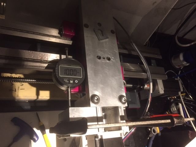
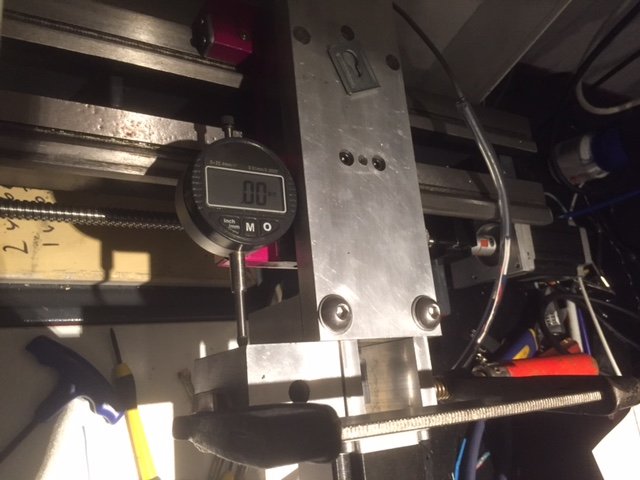
Now the stepper is installed and wired to the G540. Then I set the steps per mm, then checked backlash. I jogged the axis in, then set the dial indicator to zero and than ran in 10mm (IMG 22) then back 10mm (IMG 23) with a G0 code. This shows zero backlash, so I'm a happy camper. This is much better than my mill which is geared 2:1 with a timing belt.
Video 1 shows the X axis moving with a G0 code! There is 80mm of travel, heaps for a lathe of this size.
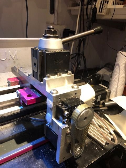
All good things must come to an end, and that was the case for my 8mm ballscrew! After about a year of use, the ballnut suddenly disintegrated! I am rebuilding the X axis to use a 12mm ballscrew connected by timing belt. Pics to follow soon.
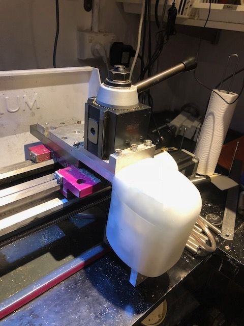
The new 12mm ballscrew is much more durable than the original, fitting it was not too difficult. This now has a 2:1 pulley system with a timing belt. The plastic cover attaches with Velcro and was cut from a 2 litre plastic milk bottle!


